Data Flow Diagram Symbols and Rules
Bijan Elahi in Safety Risk Management for Medical Devices 2018. Create Color CompositeCreates a three-band raster from a multiband raster dataset in which each band can use an algebraic.

Flowchart Symbols Meaning Complete Guide 2022
Flowchart Symbols Components.
. Operational data temperature pressure mass flow rate. A Cumulative Flow Diagram CFD is an area chart that shows the various statuses of work items for an application version or sprint. A PFD helps with the brainstorming and communication of the process design.
Logical DFD focuses on the transmitted information entities receiving the information the. They define the components of your flowchart and each symbol represents something unique. Industrial controls design specialists including schematic wiring diagram bill-of-materials wire fromto list and panel layout since 1988.
When it comes to system construction a class diagram is the most widely used diagram. Although these are the standard symbols available in most flowchart software some people do use different shapes for different meanings. Level 1 data flow model diagram example in PDF with an explanation.
A column on your board. It uses defined symbols like rectangles circles and arrows plus short text labels to show data inputs outputs storage points and the routes between each destination. The examples in this flowchart tutorial will stick with the standard symbols.
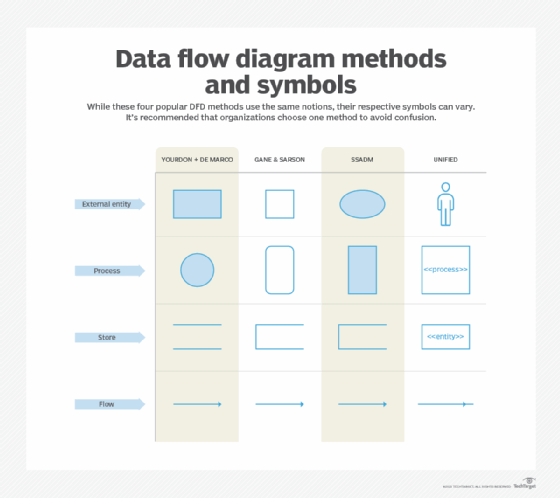
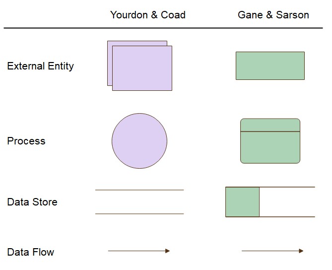
The most common example of this is using circles to denote start and end. Our DFD shape libraries contain standard symbols for both Gane-Sarson and Yourdon-Coad methodologies allowing you to create clear and consistent data flow diagrams online in minutes. DFD describes the processes that are involved in a system to transfer data from the input to the file storage and reports generation.
Physical DFD focuses on how things happen by specifying the files software hardware and people involved in an information flow. New raster functions include the following. We make use of First and third party cookies to improve our user experience.
Add shapes and symbols. Rules and symbols for creating DFD. What is data flow diagram.
Experienced with DIN IEC AS and US. Gane-Sarson notation was introduced in Chris Gane and Trish Sarsons 1977 book Structured Systems Analysis. Read our brief guide to flowchart symbols above to familiarize yourself with the most common shapes and symbols before continuing with this step.
The horizontal x-axis in a CFD indicates time and the vertical y-axis indicates cards issues. Our flowchart library comes with all the standard flowchart symbols and vertical horizontal swimlanes so you can map out any process with ease. UML Class Diagrams is a type of static structure diagram that is used for general conceptual modeling of the systematics of the application.
Such a diagram would illustrate the object-oriented view of a system. Data flow chart - represents how data is processed within a system. A new SAR synthetic aperture radar category was added to the suite of raster functions.
A data flow diagram tool allows you to take any flow of information for a process or system and condense it into a coherent. Context data flow diagram example in PDF with an explanation step by step. Using any conventions DFD rules or guidelines the symbols depict the four.
As such in most cases you dont need to worry too much about the standards and rules of all the flow chart symbols. Data flow diagrams are used to graphically represent the flow of data in a business information system. A data flow diagram DFD is a graphical or visual representation using a standardized set of symbols and notations to describe a businesss operations through data movement.
Before you embark on creating a data flow diagram it is important to determine what suits your needs between a physical and a logical DFD. Rules and symbols are available from standardization organizations. Flowchart is a very intuitive method to describe processes.
A data flow diagram DFD maps out the flow of information for any process or system. The differences and symbol rules are divergent enough to make it difficult for technologists to read the DFDs of methodologies theyre not familiar with. The process flow diagram below is an example of a schematic or block flow diagram and depicts the various unit processes within a.
12713 Process Flow Diagram. The object orientation of a system is indicated by a class diagram. The PFMEA process needs a complete list of tasks that comprise the.
Add specific rules within the. By using this website you agree with our Cookies Policy. How to draw DFD online.
Shapes and symbols play a vital role in any flowchart. In fact a simple flowchart constructed with just rectangular blocks and flowlines can already get most jobs done. Best software tools and solutions.
How do you draw a flowchart. Process Flow Diagrams PFDs are a graphical way of describing a process its constituent tasks and their sequence. Or flow chart software using a library of chemical engineering symbols.
Swimlane flowchart - illustrates process steps along with responsible owners or departments. Definition advantages and disadvantages a tutorial for beginner. How to Draw a Flowchart.
Each colored area of the chart equates to a workflow status ie. AutoCAD Electrical training courses and training material including on-site. Four SAR processing raster functions previously in the Correction category were moved to the SAR category.
Agree Learn more Learn more. Electrical Computer-Aided Design Consulting for AutoCAD AutoCAD Electrical 2017 ToolboxWD VIAWD and Promis-e.
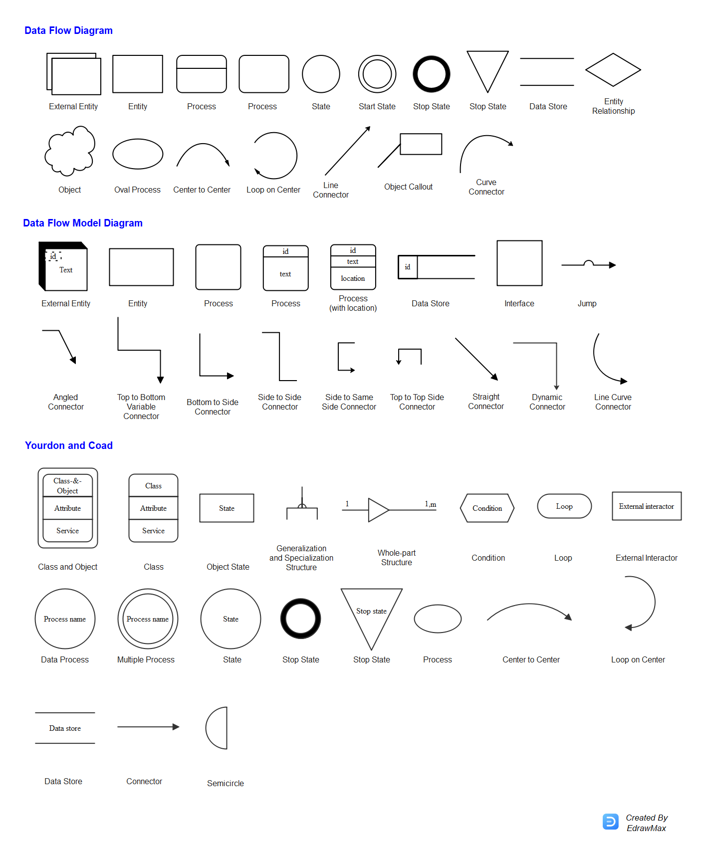
Data Flow Diagram Dfd Symbols Edrawmax
Data Flow Diagram Dfd Symbols Edrawmax
What Is A Data Flow Diagram Dfd

Data Flows Common Dfd Mistakes
No comments for "Data Flow Diagram Symbols and Rules"
Post a Comment